The RF model
The same three access points can read 61% or 15% coverage. The difference is the model, not the design.
Whose device is the heatmap drawn for?
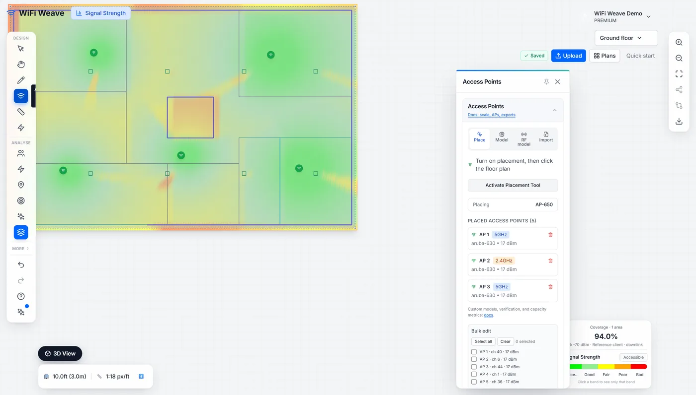
By default, a reference client — an ideal measurement device. Real devices hear less, and the client device profile shifts the whole prediction to the device that will actually be used.
| Client device | Receive offset | Transmit power |
|---|---|---|
| Reference client | 0 dB | 20 dBm |
| Laptop | −2 dB | 17 dBm |
| Tablet | −3 dB | 15 dBm |
| Smartphone | −4 dB | 14 dBm |
| VoIP handset / badge | −6 dB | 12 dBm |
| IoT sensor | −8 dB | 10 dBm |
Why check the uplink as well as the downlink?
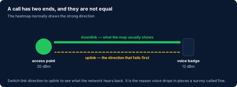
Because a call has two ends and they are not symmetrical: an access point transmits at around 20 dBm while a badge transmits at 12. Switching link direction to uplink shows what the network hears back from the device — which is what actually fails when voice drops in a place the survey called fine.
Which path-loss model should I use?
Use free-space for open areas and ITU-R P.1238 for anything with structure in it; then set the environment preset so the clutter matches the building.
| Setting | Use when |
|---|---|
| Free-space (FSPL) | Open warehouse floors, outdoor, line of sight |
| ITU-R P.1238 (indoor) | Offices, classrooms, clinics, anything partitioned |
| Environment preset | Adjusts clutter loss and the distance exponent — office, warehouse/industrial, and outdoor presets |
| Edge diffraction | Softens hard shadows at wall ends, where signal really does bend |
Which throughput model should I use?
Use the standards-based model when you are promising a number. "Estimated tiers" maps signal to a rate band; "standards-based" derives the rate from SNR using the access point's Wi-Fi standard, channel width and spatial streams.
Do these settings change the coverage percentage?
Yes. The coverage percentage is computed with the same model as the map, so the number in the corner and the picture always agree — including after you change the client device, link direction, path-loss model, environment preset or diffraction.
Common questions
How do I stop guessing at the model?
Take measurements and calibrate. Survey calibration derives the path-loss exponent and a correction surface from real readings — see survey calibration.